Grid scale energy storage system planning - Guidance for fire and rescue services
Introduction
The following guidance for fire and rescue services was approved for publication in December 2025. It replaces guidance that was first published in 2023, on which we consulted during 2024. We thank all those who responded.
A summary of the changes that have been made to the revised guidance can be viewed here.
NFCC also published a policy position statement on Battery Energy Storage Systems in October 2025, which sets out our recommendations to the UK Government and Devolved Administrations to minimise BESS fire safety risks Battery Energy Storage Systems – NFCC.
Any queries should be directed to: bess.queries@nfcc.org.uk
Foreword
For many years, the UK has generated electricity to the national electricity transmission and distribution system using predominantly coal, gas, and nuclear fired power stations. As part of the transition away from fossil fuels, 46% of the UK’s energy in the first quarter of 2025 was generated using renewable forms of energy such as solar, hydro, or wind power (UK Energy Trends, Jan–Mar 2025, Department for Energy Security and Net Zero (DESNZ)).
However, unlike traditionally fuelled power stations, renewable energy sources cannot simply be activated to meet changing levels of grid demand. Therefore, to ensure a stable supply and to cope with fluctuations in demand, the energy needs to be captured and stored. Large batteries are being deployed as energy storage devices that can capture the energy in times of low demand. Consequently, they can provide almost instantaneous support to the National Grid at times of high demand.
At present, the main legislative oversight of the development of battery energy storage system (BESS) sites is through the local government planning system. In 2023, the government’s current planning practice guidance for renewable energy was updated. As a result, early discussion is encouraged between developers of BESS and planners, as well as with the local fire and rescue service.
In publishing this guidance, NFCC seeks to support fire and rescue services to ensure they are aware of the location of all grid-scale BESS in their area. This is to enable effective operational pre-planning to take place, as and when information becomes available.
The process for a BESS to become operational can take years. Fire and rescue services should be aware that some information may be unavailable during the early stages of a site’s development. Likewise, technology may also change over the course of the development.
The aim of this guidance is to ensure that fire and rescue service requirements are proportionate to the hazard and risk present on site, without placing an undue burden on the developer of the BESS installation. It is hoped that the guidance will promote a consistent approach across fire and rescue services.
This guidance outlines that developers and operators should undertake a comprehensive risk management process, supported with appropriate evidence, to identify hazards and risks specific to the facility. This will include developing, implementing, maintaining, and reviewing risk controls. From this process, a robust outline battery safety management plan and emergency response plan should be developed in conjunction with the local fire and rescue service.
This guidance supersedes and seeks to build on the original NFCC guidance document that was published in 2023 (version 1). The guidance is based on a range of supporting materials including academic research, national and international standards, case studies, and industry guidance (please refer to Bibliography). The content of this guidance reflects analysis of that supporting material, informed by professional judgement. Future iterations of this guidance will include updated research as this becomes available.
Every BESS installation will be different. Where it is necessary to deviate from this guidance, advice should be sought from a competent person. Competency can be described as the combination of training, skills, experience and knowledge that a person has, and their ability to apply these to perform a task safely, as defined by the Health and Safety Executive (HSE). Please contact NFCC if you have any questions on the content of this guidance.
1. Scope
1. Scope
This guidance, produced by the National Fire Chiefs Council (NFCC), is for the use of fire and rescue services across the UK. It is intended to be informative, and to support the safety of community and operational personnel. It does not constitute formal legal advice; all parties’ legal duties remain as defined by law.
This guidance relates to battery energy storage systems (BESS) which are deployed in open air environments, with an energy capacity of one megawatt hour (MWh) or greater using lithium variant batteries. The principles outlined in this guidance may also be relevant to other battery technologies. However, advice should be sought from a competent person.
The use of this guidance by fire and rescue services will vary based on local context. Local planning authority (LPA) departments should, therefore, not use the guidance as a mandatory set of recommendations and instead prioritise discussions with the local fire and rescue service. NFCC recognises the pace at which technology is advancing, and this guidance is offered for fire and rescue services to use in the absence of any central government guidance.
NFCC recognises that BESS may also be deployed to support industry where there is not a connection to the national electricity transmission and distribution system. For example, this may be relevant where a site has its own methods of generating energy and intends to store it. The principles of this guidance may also be relevant in such cases.
Domestic BESS are outside the scope of this guidance. A publicly available standard, PAS 63100:2024, sets out good practice in this area.
Mobile and temporary BESS deployments are also outside the scope of this guidance. However, some principles outlined within it may still be useful to support fire and rescue services in this area.
2. Principles
2. Principles
This guidance has been developed with the safety of the public and emergency responders in mind. It is intended to help reduce the risk to as low as reasonably practicable (ALARP). At the same time, it recognises that ultimate responsibility for the safe design and running of these facilities rests with the developer and operator.
These guidelines provide a basis for assessing planning proposals and, as such, cannot cover every eventuality or type of design.
In developing these guidelines, the hazards and risks from lithium variant batteries identified in NFCC Operational Guidance (Utilities and fuel: Rechargeable batteries) have been considered.
The following principles, adapted with minor amendments from guidance on renewable energy facilities produced by the Australian state of Victoria (County Fire Authority), form the basis of this guidance. They should be considered by fire and rescue services when liaising with operators:
- Effective identification and management of hazards and risks specific to the siting, infrastructure, layout, and operations at the facility.
- Siting of renewable energy infrastructure to eliminate or reduce hazards to emergency responders.
- Safe access for emergency responders in and around the facility, including to renewable energy and firefighting infrastructure.
- Provision of adequate water supply and firefighting infrastructure to allow safe and effective emergency response. This could include the provision of water to allow for defensive firefighting to protect surrounding infrastructure.
- Siting and management of vegetation to avoid increased wildfire risk.
- Prevention of fire ignition on-site that could spread to BESS and associated infrastructure (for example, inverters, switchgear, and transformers).
- Prevention of fire spread between site infrastructure (for example, solar panel banks, wind turbines, battery containers/enclosures, transformers, inverters, and switchgear).
- Prevention of external fire impacting and igniting site infrastructure.
- Provision of accurate and current information for emergency responders during emergencies.
- Effective emergency planning and management, specific to the site, infrastructure, and operations.
3. Organisational requirements for fire and rescue services
3. Organisational requirements for fire and rescue services
Fire and rescue services can take measures to support the planning process. This includes facilitating timely and meaningful engagement between the fire and rescue service, local planners, and developers to assist operational pre-planning.
Fire and rescue services are encouraged to:
- nominate a lead department within their service that will be the public-facing external point of contact for BESS. It is likely that Protection and Operational Policy staff will both have a role in responding to the consultation and dealing with the operational pre-planning elements.
- host a webpage on their fire and rescue website with point of contact details for BESS engagement.
- establish and maintain working arrangements with colleagues in local LPA departments to facilitate efficient consultation with regard to BESS. Although fire and rescue services are not a statutory consultee for planning, this would represent good practice.
- use this guidance to raise hazard awareness and inform discussions with developers.
4. Planning approval process
4. Planning approval process
As BESS are classed as infrastructure projects, they progress via a planning application route for approval. They are not dealt with via Building Regulations (as amended) consultations, unless there are ancillary buildings on site which may be covered. As such, the fire and rescue service are not a statutory consultee in planning applications for BESS sites. BESS sites are not categorised as Nationally Significant Infrastructure Projects (NSIP) for the purpose of planning.
The UK government’s planning practice guidance for renewable energy encourages both planners and developers to engage with the local fire and rescue service when planning new sites. As such, fire and rescue services should be part of early conversations regarding BESS proposals. This should continue throughout the development and into the operational phase.
Whilst fire and rescue services are not a statutory consultee for planning, they do have a statutory responsibility under the Fire and Rescue Services Act. This includes obtaining information to assist with the extinguishing of fires, and the protection of life and property in their area. Fire and rescue services in devolved administrations should consult their relevant equivalent legislation.
In addition, through engaging at the pre-planning or planning stage, fire and rescue services may be able to give advice about the design and layout of the site to aid operational pre-planning.
It is expected that the number of BESS developments across the UK will increase significantly. Fire and rescue services may also seek to ensure they are aware of planned and operational projects in their area. The Department for Energy Security and Net Zero (DESNZ) maintain a database of Renewable Energy Schemes for this purpose.
5. Information requirements
5. Information requirements
Grid-scale BESS should form part of fire and rescue service planning in accordance with arrangements required under Section 7(2)(d) of the Fire and Rescue Services Act. Incidents involving BESS will require a hazardous materials response. Site specific risk information (SSRI) should therefore be gathered with the support of suitably trained fire and rescue service hazardous materials advisors (HMA), and made available to operational fire crews.
6. System design, construction, testing and decommissioning
6. System design, construction, testing and decommissioning
BESS can come in a wide variety of designs, from large shipping containers to multiple smaller enclosures. BESS can either be accessed by an internal access route (Figures 1 and 2) or from the outside (Figure 3).
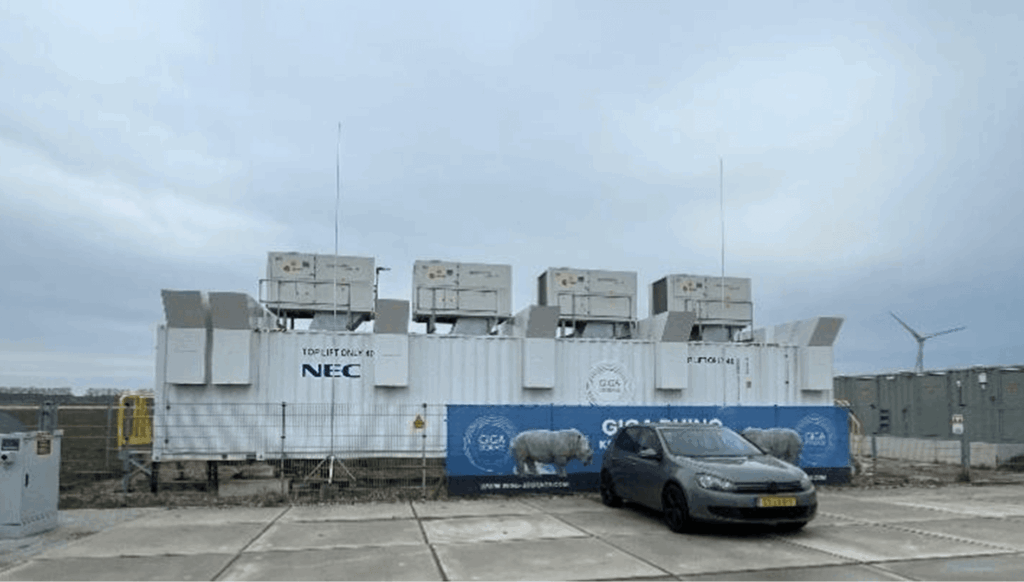
Figure 1: Containerised BESS unit requiring internal access. Image reproduced with permission of Pacific Northwest National Laboratory (PNNL).
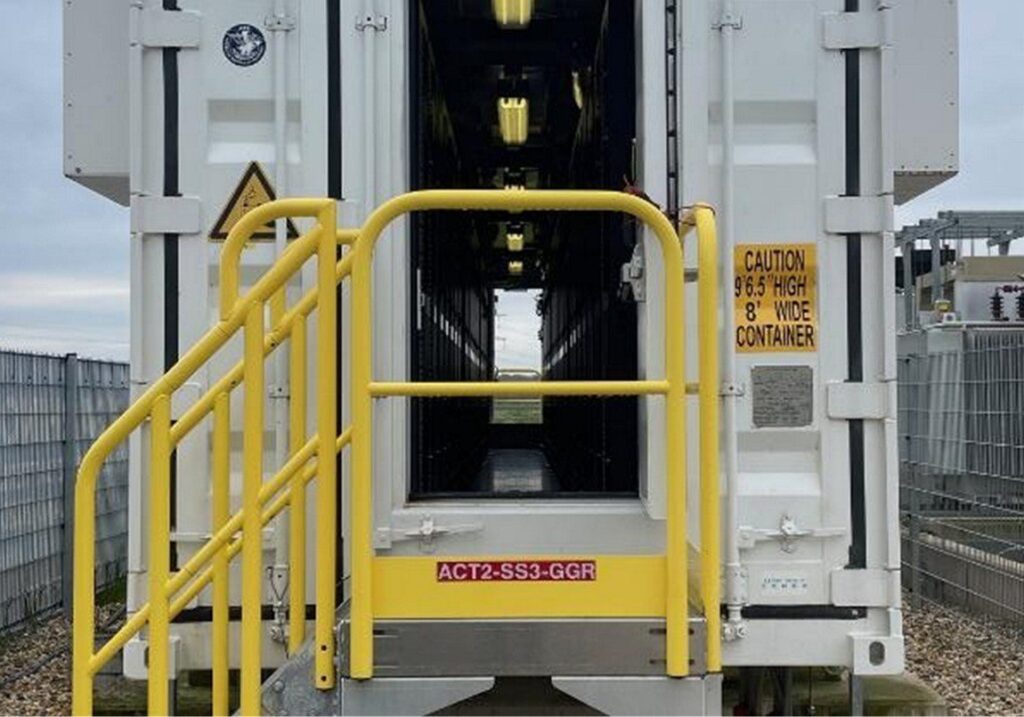
Figure 2: Internal corridor of a BESS unit accessed via gated steps. Image reproduced with permission of PNNL.
More modern designs feature a cabinet design accessible via doors on the outside of the BESS unit (Figure 3). In these cases, it is not necessary to enter the unit.
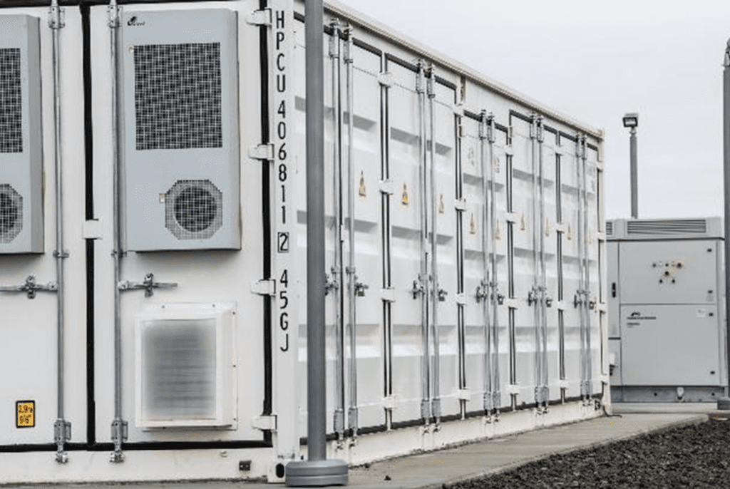
Figure 3: Cabinet-style BESS with external access. Image reproduced with the permission of PNNL.
Fire and rescue services should seek to obtain as much information as possible at the earliest opportunity to enable an initial appraisal of the BESS. It is the responsibility of the applicant / developer / designer / manufacturer to provide this information to the fire and rescue service. Additionally, they must provide the fire and rescue service with appropriate evidence to support any claims made on performance, and cite appropriate standards for installation.
Fire and rescue services should recognise that the development timeline of some projects may span several years. Consequently, initial information may be provided at the outline stage, with more detailed information following as the project progresses. This information should be made available to operational risk teams within fire and rescue services for inclusion in SSRI records.
The fire and rescue service may wish to clarify the following areas with the site developer at the pre application/engagement phase:
- Thermal events and events leading to deflagration:
- How will the proposed BESS perform in a thermal event / deflagration, and what proactive or reactive systems are proposed to mitigate this?
- How will the thermal event be contained to the BESS cabinet of origin without the radiant heat affecting other cabinets?
- How has the performance of the BESS in a thermal runaway event influenced site design?
- Has the proposed equipment undergone any full-scale fire testing or has it been certified by a reputable body such as Underwriters Laboratory (UL 9540A)?
- Site plans:
- What are the assumptions about active firefighting within the emergency response plan, and what measures are in place to reduce the scale of an incident?
- Are the incident assumptions realistic? What is the role of the fire and rescue service at an incident? Are they realistic? What is the expectation of the fire and rescue service in terms of the fire strategy at a thermal event?
- What is the provision for firefighting access to, around, and within the site?
- Water supply and suppression systems:
- What is the type, purpose, and effect of any fire suppression system installed?
- What is the purpose of the water supply provision on site? Is it intended for boundary cooling / defensive firefighting or active suppression?
- How will water run-off be managed?
- BESS design:
- What is the size, quantity, and capacity of each BESS unit?
- Is the BESS design appropriate for the weather at the proposed location in terms of preventing water ingress and impact of temperature range on cooling systems?
- Does the applicant / developer have relevant competence and experience in the field of BESS design and deployment on the scale of the proposed development? If not, do they have access to specialist advisors to support?
- What are the arrangements for ongoing monitoring of the BESS?
- What is the response time for onsite technical assistance in the event of an incident?
- Detection and monitoring:
- How will the BESS and associated equipment be monitored, and what is the process for alerting the fire and rescue service?
- How will the fire and rescue service align their approach to handling calls to BESS sites to their unwanted fire signals position?
- Environmental receptors (please refer to sections 17 and 18 of this guidance for details).
Responses to these questions will assist in creating an emergency response plan.
This information is based on similar guidance published by the Environment Agency (Fire Prevention Plans: Environmental Permits guidance). This details what should be included in a fire prevention plan, the fire prevention measures that should be put in place, a plan template, and examples of alternative measures. Equivalent guidance should be sought in devolved administrations.
7. Battery chemistry
7. Battery chemistry
Battery chemistry is a highly specialised area of materials science. As such, NFCC is not an authoritative body on the subject matter and can only comment on the broad and generally accepted principles of battery chemistry. These form part of the 2024 report ‘Health and Safety Guidance for Grid Scale Energy Storage Systems’’, produced by Frazer-Nash Consultancy on behalf of DESNZ. The following text relating to battery chemistry principles, taken from this report, is reproduced here with the permission of DESNZ:
There is a range of battery chemistries available which suit different use cases, have a different maturity and which present different risks and safety profiles that are at varying states of maturity.
Lithium-ion batteries make up the majority of the current grid-scale BESS global market share, due to their ideal characteristics of high-energy density, high-energy efficiency and a long-life cycle.
There are multiple variants of lithium-ion batteries, with lithium nickel manganese cobalt oxide (NMC) and lithium iron phosphate (LFP) the two main chemistries that dominate stationary lithium-ion energy storage projects. There are multiple trade-offs when selecting battery cell types, including power and energy density, availability, cost and safety. From a safety perspective, it is noted that LFP batteries typically have better thermal stability (lowering the probability of thermal runaway) than NMC batteries, but not removing it.
‘Health and Safety Guidance for Grid Scale Energy Storage Systems’ (2024), Frazer-Nash Consultancy.
While characteristics of lithium-ion batteries can vary depending on their chemistry, the overall hazards they pose to personnel during a fire are broadly similar.
Specifically, they may all involve toxic, flammable and/or explosive vapour clouds. They may also result in intense flaming combustion.
In 2023, the Research Institute of Sweden (RI.SE) published the report ‘Guidelines for the fire protection of battery energy storage systems’’ (RI.SE report 2023:117). The report highlighted examples of cause scenarios and their associated possible consequences related to BESS. These are listed below, in no particular order:
Cause scenarios:
- Manufacturing or installation errors
- Damage to battery cells due to environmental effects (for example, dust, humidity, salt water, and lightning strikes)
- Electrical faults such as overcharging or deep discharge, electrical arcs
- Ageing and lithium dendrite formation
- Mechanical impact (for example, collisions, and ice from wind turbines)
- External fire spreading to the BESS
- Over/under-temperatures
- Incidents caused by human factors during maintenance
- Vandalism, cyber attacks
Possible consequences:
- High temperatures
- Fire
- Explosion
- Pressure buildup
- Release of toxic gases
- Projectiles
- Electrical hazards
- Corrosive gases
- Chemical spill
8. Detection and monitoring
8. Detection and monitoring
An effective and appropriate method of early fault detection within the batteries should be in place, making it possible to immediately disconnect the affected battery/batteries remotely. This may be achieved through an effective battery management system (BMS).
There are specific systems that detect the early components of electrolyte degradation and ‘off gassing’, which may be helpful as an early warning. However, these systems should not be relied on alone to predict or prevent a thermal event.
Temperature detection via the BMS is also a critical first warning of thermal runaway.
The risk management process should include detection systems to alert the operator of an event at the site.
Appropriate automatic detection such as smoke, gas, or radiant heat detectors, as well as continuous combustible gas monitoring within BESS cabinets/enclosures should be provided in all BESS. Where systems are installed, gas detectors should alarm when flammable gas is detected, shut down the BESS, and initiate full exhaust ventilation. Sensor placement should ensure that gases are detected quickly enough for an effective response. Sensor placement should take into account the device’s response times and the type of gas being monitored (for example, hydrogen, carbon monoxide, or other volatile organic compounds).
As an alternative to actively managing the release of flammable gas, deflagration panels could be used to deal with any over-pressurisation of the BESS cabinet/enclosure. Any deflagration panels present should be conspicuously indicated.
External audible and visual warnings should be clearly visible to operational crews, along with addressable identification, control, and indicating equipment. This equipment should be linked to:
- Battery management system (when a thermal runaway event is identified)
- Detection and suppression system activation
This will help operational crews understand what the warning relates to, improving their decision-making and incident planning.
9. Suppression systems
9. Suppression systems
Suppression systems will either use inert gas or aerosol suppression, or water-based suppression. The type of suppression system should be dictated by the battery technology used within the BESS, and not by site conditions or constraints. For example, gaseous suppression should not be used to compensate for the lack of availability and accessibility of water supplies at a particular site.
It is becoming increasingly common for BESS to be designed and manufactured without any suppression system, and to be specifically designed so that a fire can be contained within the BESS cabinet/enclosure. Even in cases where no water-based suppression system is installed, local water sources will always be needed for exposure protection to limit cabinet-to-cabinet fire spread.
The primary role of a fire suppression system in a BESS is to prevent a fire in the ancillary electrical equipment spreading to the battery modules. It may have a limited effect to protect the BESS from an external fire spreading to it. All claims of performance of suppression systems need to be supported with appropriate evidence for that specific use case.
The suppression system, regardless of type, will have little effect on a thermal event within the battery cell. Their primary function is to help prevent cell to cell propagation, rather than fully extinguishing a fire in the cell. The suppression system may, however, offer the advantage of dealing with fires occurring elsewhere within the BESS cabinet that are unrelated to the lithium battery.
A developer may propose that suppression systems are not required in the design. In such cases, the fire and rescue service should be satisfied that alternative controls are in place to prevent a fire or other thermal event in the BESS cabinet/enclosure of origin, from propagating to adjacent equipment.
Inert gaseous and aerosol suppression system
Gaseous suppression systems have limited cooling ability and cannot suppress thermal runaway, which will continue even without oxygen. Their use, however, has been effective in managing flaming combustion within enclosed spaces, which may make them more suitable for use in certain ancillary electrical systems.
The design and selection of a gaseous suppression system should be specific to the use of the BESS in question and designed by a competent person. Whilst a suppression system may extinguish the flaming combustion within a BESS, it could create a further complexity. In some cases, it can contribute to the formation of an explosive vapour cloud, as occurred in the McMicken incident in Surprise, Arizona in 2019.
Water-based suppression system
Water has a high cooling capability and therefore may be able to prevent further cell to cell propagation and thermal runaway within a BESS. However, it is also conductive and has in some cases caused additional damage and increased incident duration.
Water-based systems could be installed in one of two ways:
- As a wet pipe system with a dedicated water supply
- As a dry pipe system with a standard instantaneous firefighting connection for the fire and rescue service to connect to from a distance.
Where dry pipe or fire service inlets are provided for BESS cabinets/enclosures, they should be clearly marked with appropriate signage in a prominent position for the fire and rescue service to use. This signage should clearly indicate which cabinets/enclosures each inlet serves. For sites where a dry pipe system is installed, the following considerations apply:
- Fire and rescue service attendance is dependent on many factors. The developer and the relevant fire and rescue service should discuss attendance expectations early in the planning process, as response times and weight of attendance will vary between services.
- Fire and rescue service inlets need to be positioned where operational crews are safe from the effects of a BESS event. Poor placement may render the system unusable.
- An appropriately sized water supply must be provided in a location that allows quick access for the fire and rescue service.
Any calculations to determine the required water supply for an appropriate suppression system should be completed by a competent person. They should take into account the appropriate risk and duration of any fire.
Where water-based suppression systems are incorporated, their use should be accompanied by a plan to contain any contaminated fire water run-off.
10. Explosion control (deflagration protection)
10. Explosion control (deflagration protection)
Explosive vapours will be produced which – through the process of thermal runaway, and depending on the battery chemistry – may transition to flaming combustion, or remain as a vapour cloud that could lead to an explosion hazard that personnel need to be aware of.
BESS containers should be fitted with explosion protection or deflagration venting appropriate to the hazard and battery technology deployed. Designs should be developed by competent persons, with design suitability able to be evidenced by utilising British Standards or equivalent National Fire Protection Association (NFPA) Standards, as follows:
- BS EN 16009:2011 Flameless Explosive Venting Devices
- BS EN 14373:2021 Explosion Suppression Systems
- BS EN 14797:2007 Explosion Venting Devices
- NFPA 68 Standard on Explosion Protection by Deflagration Venting
- NFPA 69 Standard on Explosion Prevention Systems
Exhaust systems designed to prevent deflagration should keep the environment below 25% of the lower explosive limit (LEL).
Flames and materials discharged during venting should be directed safely outside. Measures must be in place to ensure they do not cause fire spread beyond the affected unit, or pose additional risks to people near the originating BESS cabinet or enclosure. The likely path of any vented gases or materials should be identified in emergency response plans to reduce the risk to responders.
The position of any venting should take account of the likelihood of weather-related ingress of water. The aim is to minimise the risk of water damage during the ordinary functioning of the BESS.
Designs should also give consideration to leakage paths for explosive vapour via cable trunks and routes to other structures, which could result in a secondary remote vapour cloud explosion, as in the Dahongmen incident in Beijing in 2021.
Explosion/deflagration strategies should be built into the emergency response plan to ensure that responders understand the strategies and how their actions may influence them. For example, personnel may open the door to a unit, which may negate the potential effect of deflagration vents due to an alternative path of least resistance having been created.
Where emergency ventilation is used to mitigate an explosion hazard, the isolation/disconnect for the ventilation system should be clearly marked. Signage should warn personnel or operational crews not to disconnect the power supply to the ventilation system during an evolving incident (NFPA (2023) Standard for the Installation of Stationary Energy Storage Systems, paragraph G.1.4.3.3). The remaining unaffected cells need to continue to be maintained within their operating temperature.
The chosen method of explosion control system should be supported by evidence from a competent person or an approved institution, such as Underwriters Laboratories (UL) or the NFPA.
Site location
The potential impact of an incident on the local environment should factor into the choice of BESS site and its associated safety measures. The developer should produce a plan that identifies all sensitive receptors within a 1km radius of the site. This plan should support discussions with planners and other stakeholders regarding site suitability and inform appropriate emergency planning.
The Environment Agency’s Fire Prevention Plans: Environmental Permits Guidance provides examples of sensitive receptors that may include:
- Schools, hospitals, nursing and care homes, residential areas, and workplaces
- Protected habitats, watercourses, groundwater, boreholes, wells, and springs supplying water for human consumption (Further habitat information can be found on the Department for Environment, Food and Rural Affairs (Defra) MAGiC map)
- Roads, railways, bus stations, pylons (on or immediately adjacent to the site only), utilities, and airports
Any plans created should include a compass rose showing north and the prevailing wind direction.
Whilst incidents involving BESS are relatively rare at the time of publication, they can result in extended disruption and may impact business continuity in the adjacent area. Since UK fire safety principles and design documents are based on the assumption that an incident or fire will occur (typically one fire at one time), applicants or developers should assess the potential impact of such an incident on the surrounding area. This should include consideration of business continuity, neighbourhood disruption, and wider impact. The assessment should be inextricably linked to the battery technology type, the expected incident response from the fire and rescue service (controlled burn or active firefighting), and the proximity of any significant transport infrastructure and public buildings.
The assessment should recognise that any incident may last several hours. It should outline any disruption to the local and/or national economy.
Where there are concerns that a potential toxic vapour cloud could affect nearby sensitive receptors, developers may also wish to commission an analysis of fire gas plume modelling under different scenarios. This helps to understand the impact on local communities from conditions such as prevailing wind. Such modelling, if undertaken, should be completed by a competent person.
External factors also need to be considered, including proximity of other BESS sites and the risk to the site from surface water flooding or spread from wildfire.
11. Access
11. Access
Site access
Suitable facilities for safe access and egress to the site should be provided. Designs should be developed in close liaison with the local fire and rescue service, as specific requirements may apply due to variations in vehicles and equipment.
Achieving adequate vehicular access for the fire and rescue service prevents personnel from having to enter the BESS site and drive through a vapour or gas cloud to reach the scene of operation. It is therefore preferable to have an alternative access point, taking account of the likely wind direction. If the provision of an alternative access point is not practicable, an alternative may be to provide a perimeter ‘loop’ type of vehicle access around the site.
Whilst the BESS approval process is via the planning route, there is an absence of guidance regarding adequate access for the fire and rescue service. However, the principles contained within Approved Document B in support of B5 may assist in providing proportionate and adequate access and facilities for the fire and rescue service. It should, however, be acknowledged that the guidance referenced below is intended for ‘common building situations’. As BESS clearly do not fall into this category, the guidance is cited only as potential broad principles.
Section 15 of Approved Document B Volume 2: Buildings other than dwellings sets out a number of tables relating to access routes and hard standing areas that consider the dimensions of fire service vehicles.
Table 15.2 of Approved Document B, reproduced in Table 1 below, provides an overview of access routes and hard standing areas which have given consideration to fire service vehicle dimensions:
| Appliance type |
Minimum width of road between curbs (m) |
Minimum width of gateways (m) |
Minimum turning circle between kerbs (m) |
Minimum turning circle between walls (m) |
Minimum clearance height (m) | Minimum carrying capacity (tonnes) |
| Pump | 3.7 | 3.1 | 16.8 | 19.2 | 3.7 | 12.5 |
| High reach | 3.7 | 3.1 | 26.0 | 29.0 | 4.0 | 17.0 |
Table 1: Typical fire and rescue service vehicle access route specification, reproduced from Approved Document B (Table 15.2)
Notes:
- Fire appliances are not standardised. The building control body may, in consultation with the local fire and rescue service, use other dimensions.
- The road base can be designed to 12.5 tonne capacity. Structures such as bridges should have the full 17 tonne capacity. The weight of high reach appliances is distributed over a number of axles, so infrequent use of a route designed to accommodate 12.5 tonnes should not cause damage.
Diagram 15.3 from Approved Document B provides a schematic demonstrating a dead-end situation:
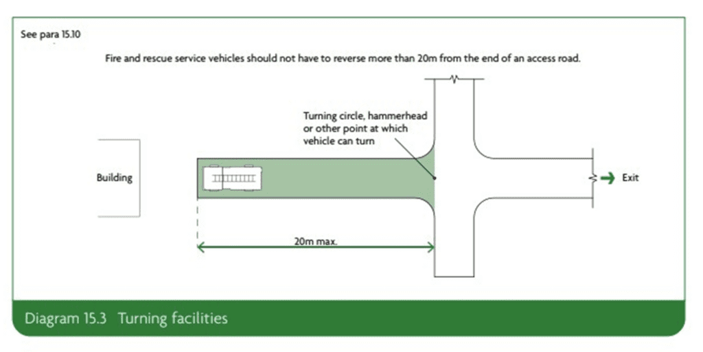
Figure 4: Schematic demonstrating a dead-end situation, reproduced from Approved Document B (Diagram 15.3: Turning facilities)
This diagram illustrates the required turning facilities for fire and rescue service vehicles near buildings. It shows a straight access road leading to a building on the left-hand side. At the end of the access road, adjacent to the building, a fire engine is depicted in a designated area.
The key requirement highlighted is that fire and rescue vehicles should not need to reverse more than 20m from the end of an access road. To comply with this, a turning facility must be provided. The diagram shows a T-shaped junction at the end of the access road, referred to as a “turning circle, hammerhead or other point at which a vehicle can turn”, allowing the vehicle to safely turn around. The maximum distance allowed between the end of the access road and the turning point is labelled as “20m max”.
12. Spacing between BESS
12. Spacing between BESS
The emergency response plan should assume that the fire will not spread beyond the BESS container of origin. Fire and rescue operations should be limited to boundary cooling of surrounding BESS and monitoring the BESS involved in the thermal event.
This outcome can be achieved through a number of different routes, including:
- Adequate separation between the BESS enclosure/cabinet to ensure that the radiant heat from a thermal event in one BESS enclosure/cabinet will not trigger a secondary event, and
- Provision of fire-resistant materials that will prevent direct flame impingement or radiated heat affecting adjacent BESS and prevent the incident developing beyond BESS of origin.
The provision of a suppression system to the BESS cabinet/enclosure is unlikely to compensate for reduced spacing between BESS.
A BESS enclosure may have been tested to a standard such as UL 9540A. If this shows that propagation does not occur between BESS cabinets/enclosures, it is possible to reduce separation to a minimum of 3ft or 0.914m as set out in NFPA 855: Standard for the Installation of Stationary Energy Storage Systems (2023) (NFPA standards can be viewed online for free by registering on their website). Any further reductions in distance should only be made based on technical advice from a competent person.
It is important for the reader to consider NFPA 855 in its entirety to ensure that separation distances are not taken out of context. Section 9.4.2.2 (Annex A) of NFPA 855 further clarifies the limitations of the standard.
If the developer cannot demonstrate that a thermal event/fire can be contained to the BESS enclosure/cabinet of origin, the developer should be referred to guidance on the separation distances within the current edition of NFPA 855.
NFCC does not support vertical stacking arrangements of containers or BESS cabinets/enclosures. This is because stacking elements on top of each other increases the level of risk in terms of vertical fire spread between the BESS, fire loading, and difficulty in gaining access.
Spacing to other buildings beyond perimeter of site
Distances between BESS cabinets/enclosures and occupied buildings will vary based on individual site designs. Proposed distances should take into account risks, including the impact of any vapour cloud. Any mitigation factors that have been incorporated into the site design should also be considered.
An initial minimum distance of 30m is proposed between BESS cabinets (or associated infrastructure such as transformers and switchgear) and occupied buildings, before considering any mitigation such as blast walls. This distance is based upon the 100ft distance for remote installations cited in NFPA 855:2023.
13. Site conditions
13. Site conditions
In addition to the risk of an incident occurring within the BESS, the site needs to be maintained in order to prevent a fire spreading to the BESS, or indeed fire loading. This is because combustible materials or poor separation between BESS cabinets/enclosures can create a ‘bridge’ or path for flaming or radiant heat to travel between units.
It is important that no combustible material is adjacent to BESS cabinets/enclosures and that clear access is maintained. Areas within 3m of BESS cabinets/enclosures should be kept clear of combustible vegetation. Additionally, all other vegetation within the curtilage of the site should be managed appropriately to avoid increased risk of a fire on the site.
Areas with wildfire risk or vegetation that could result in a significant fire should be considered as part of the assessment. Additional separation distances should be included in the design to help prevent fire spread to the BESS. This also helps to avoid an increase in the ambient temperature within the BESS cabinet/enclosure beyond safe operating limits.
14. Water supplies
14. Water supplies
Pumping fire appliances in the UK typically have a water storage capacity of approximately 1,800–2,000L of water. This capacity can be exhausted in under five minutes per appliance. Therefore, an additional on-site water supply must be accessible to fire and rescue services in the event of an emergency.
There should be enough water available to meet firefighting requirements and to manage a reasonable worst-case scenario. Depending on the site, this may be provided through storage tanks, on-site lagoons, hydrants, or mains water supply.
The amount of water required will vary depending on a number of factors, including:
- The size of the incident to be dealt with, for example 1 x BESS cabinet/enclosure
- The principles set out in the emergency response plan and the expected role of the fire and rescue service (firefighting strategy)
- Access and facilities for personnel on site
- BESS cabinet/enclosure location and proximity to infrastructure or populated areas
- The requirement to supplement any on-site firefighting facility such as a dry pipe sprinkler or deluge system
Several manufacturers of BESS now advocate that if a thermal event occurs in a BESS unit and this progresses to thermal runaway, the BESS cabinet/enclosure should be allowed to consume itself or in other words, burn itself out. Furthermore, an increasing number of BESS manufacturers suggest that applying firefighting jets to the BESS cabinet/enclosure will have limited effect and could prolong the duration of the thermal event unnecessarily. In these instances, water fog or spray pattern branches should only be directed to areas to ensure the incident does not spread to adjacent BESS.
If it can be confirmed that the manufacturer’s recommended firefighting tactic for the BESS cabinet/enclosure is to defensively firefight and boundary cool whilst allowing the BESS cabinet/enclosure to consume itself without spreading to neighbouring cabinets, this may reduce the water requirements – and thus the drainage / environmental protection requirements – significantly.
Water requirements will vary depending on the layout, design and number of BESS cabinets on the site. The number of elevations that would need to be cooled to prevent fire spread should be considered in the discussions with developers.
Ingress Protection (IP) ratings of BESS cabinets/enclosures should be known, to understand the risks associated with boundary cooling.
In order to form an emergency response plan, it is imperative to follow the manufacturer’s instructions. This is to ensure that any incident is resolved swiftly and safely with minimal damage to the environment and the local area.
Any required installations of fire hydrants and connections to any dry pipe on the BESS site should comply with BS 9990 Non-automatic firefighting systems in buildings code of practice (current edition). They should be identified in accordance with BS 3251 Indicator Plates for Fire Hydrants (current edition).
Fire hydrants provided should achieve a flow rate of no less than 25L/sec at any hydrant on the site. This figure is based on the National Guidance Document on the Provision of Water for Firefighting (2025), produced by Water UK and the Local Government Association (LGA). The flow rate for transportation has been selected as the comparative value for flow rates, rather than that of a domestic housing development or an industrial setting.
Where a flow of 25L/sec cannot be achieved, it would be prudent to provide an equivalent static supply of water on site that will provide for the same flow rate for a duration of 120 minutes. This equates to approximately 180,000L of water. The management of water run-off should be considered as part of the site design (for example, drainage systems, interceptors, and bunded lagoons).
Water supplies for any on-site suppression system must be independently calculated by a competent fire engineer, based on the design fire size of the BESS.
Any static water storage tanks designed to be used for firefighting should be located at least 10m away from any BESS container/cabinet to allow for safe access and usage. They should be clearly marked with appropriate signage and be easily accessible to fire and rescue service vehicles. Their location should be considered as part of a risk assessed approach that takes into account potential fire development and impacts. Outlets and connections should be agreed with the local fire and rescue service. Any outlets and hard suction points should be protected from mechanical damage (for example, through use of bollards).
15. Signage
15. Signage
Signage to indicate the presence of a BESS should be installed in a suitable and visible location on the outside of BESS cabinets/enclosures. Safety signage should be installed in accordance with Health and Safety (Safety Signs and Signals) Regulations. Signage should also include of the following details:
- Relevant hazards posed
- The type of technology associated with the BESS
- Any suppression system fitted
- 24/7 emergency contact information signs on the exterior of a building or enclosure. (This should be sized such that at least one sign is legible at night at a distance of either 30m or from the site boundary, whichever is closer, as stated in NFPA 855:2023).
16. Outline battery safety management plan
16. Outline battery safety management plan
To ensure the provision of risk information to the fire and rescue service, the site operator should develop and share an outline battery safety management plan with the local fire and rescue service point of contact. The layout and design of each operator’s outline battery safety management plan will vary, but it should contain the following broad subject areas:
- How the fire and rescue service will be alerted
- A facility description, including infrastructure details, operations, number of personnel, and operating hours
- A site plan depicting key infrastructure: site access points and internal roads, firefighting facilities (for example, water tanks, pumps, booster systems, fire hydrants, and fire hose reels), drainage, and neighbouring properties
- Details of the emergency response coordinator, including the subject-matter expert for the site
- Safe access to and within the facility for emergency vehicles and responders, including to key site infrastructure and fire protection systems
- Details and explanation of warning systems and alarms on site and locations of alarm annunciators with alarm details (smoke, gas, temperature)
- Hazards and potential risks at the facility and details of their proposed management
- The role of the fire and rescue service at incidents involving a fire, thermal event or fire spreading to the site
- Emergency shutoff or isolator locations
17. Site plans and maps
17. Site plans and maps
In addition, site plans should be provided to the fire and rescue that include:
- The layout of structures
- Any areas where hazardous and flammable materials are stored on site (location of gas cylinders, process areas, chemicals, piles of combustible wastes, oil and fuel tanks)
- All permanent ignition sources on the site and show they are a minimum of 6m away from combustible and flammable waste
- Any areas where combustible waste is being treated or stored, including non-waste material
- All separation distances
- Any areas where combustible liquid wastes are being stored
- Main access routes for fire engines and any alternative access
- Access points around the site perimeter to assist firefighting
- Hydrants and water supplies
- Areas of natural and unmade ground
- The location of fixed plant or storage location of mobile plant when not in use
- The location of spill kits
- Any other relevant site-specific information
- Drainage runs, pollution control features such as drain closure valves, and fire water containment systems such as bunded or kerbed areas (this may be easier to show on a separate drainage plan)
Plans provided must show all sensitive receptors within a 1km radius of the site that could be affected by a fire. Examples of sensitive receptors may include:
- Schools, hospitals, nursing and care homes, residential areas, and workplaces
- Protected habitats, watercourses, groundwater, boreholes, wells, and springs supplying water for human consumption (Further habitat information can be found on the Defra MAGiC map)
- Roads, railways, bus stations, pylons (on or immediately adjacent to the site only), utilities, and airports
Plans should have a compass rose showing north and the prevailing wind direction.
18. Environmental impacts
18. Environmental impacts
Suitable environmental protection measures should be provided, and developers should liaise with the Water Undertakers or the Environment Agency to understand any impacts Protection measures should include systems for containing and managing water run-off. System capability/capacity should be based on anticipated water application rates, including the impact of water-based fixed suppression systems.
Sites located in flood zones should have details of flood protection or mitigation measures.
19. Recovery
19. Recovery
The operator should develop a post-incident recovery plan that addresses the potential for re-ignition of BESS and de-energising the system. The plan should also include provisions for removal and disposal of damaged equipment and contaminated fire water effluent.
20. Incident Event Database
20. Incident Event Database
Whilst, at the time of publication, thermal events and incidents involving BESS in the UK are relatively rare, there have been failures within BESS across the world.
A source of information is the Electric Power Research Institute (EPRI) Failure Event, which records Energy Storage Failure Events.
Further advice and guidance for fire and rescue services can be obtained through contacting NFCC via our website.
Bibliography
Bibliography
British Standards Institution (BSI). Electrical installations. Protection against fire of battery energy storage systems for use in dwellings. Specification. 2024. PAS63100.
British Standards Institution (BSI). Flameless explosion venting devices. Standard. 2011. BS EN 16009:2011.
British Standards Institution (BSI). Explosion Suppression Systems. Standard. 2021. BS EN 14373:2021. Explosion venting devices. 2007. BS EN 14797.
Building Regulations 2010; Fire Safety Approved Document B. 2019. Fire safety: Approved Document B – GOV.UK (www.gov.uk)
Country Fire Authority (CFA). CFA’s Design Guidelines and Model Requirements for Renewable Energy Facilities, v4 (2023). CFA. [Online] 4, 2023. https://www.cfa.vic.gov.au/plan–prepare/buildingplanning–regulations/renewable–energy–fire–safety.
Department for Energy Security & Net Zero. Energy Trends: UK, April to June 2025. Published September 2025. Energy Trends September 2025
Department for Energy Security & Net Zero/ Frazer Nash Consultancy. Smart: Energy Storage & Flexibility Innovation. Health and Safety Guidance for Grid Scale BESS 2024. Health and Safety Guidance for Grid Scale Electrical Energy Storage Systems (publishing.service.gov.uk)
Electric, China. Institute of energy storage and novel electric technology. 2021.
Firefighter Safety Research Institute. Four Firefighters Injured in Lithium-ion Battery Energy Storage System Explosion – Arizona. McKinnon, M B, DeCrane, S and Kerber, S. 2020. Report: Four Firefighters Injured In Lithium-Ion Battery Energy Storage System Explosion – Arizona
Grönlund O, Quant M, Rasmussen M, Willstrand O, Hynynen J. Guidelines for the fire protection of battery energy storage systems. RI.SE. 2023. https://urn.kb.se/resolve?urn=urn:nbn:se:ri:diva.
National Fire Protection Association. Standard for the Installation of Stationary Energy Storage Systems. Energy Storage, NFPA 855: Improving Energy Storage System Safety. 2024. NFPA855_Safety_240111.pdf (cleanpower.org)
UK Public General Acts (Legislation.gov.uk). Fire and Rescue Services Act 2004. https://www.legislation.gov.uk/ukpga/2004/21/contents.
Water UK & Local Government Association. National guidance document on the provision of water for firefighting. 2007 (Third Edition, 2025). pp. Appendix 5 (pages 37-38). National guidance document on the provision of water for firefighting | Water UK
Additional resources
Additional resources
Nederlands Instituut Publieke Veiligheid (Netherlands Institute of Public Safety) (NIPV). Report EU Energy Storage Systems Safety Conference 2023. Hessels.
December 2023. 20231218–NIPV–Report–EU–Energy–Storage–Systems–SafetyConference–2023.pdf
American Clean Power Association. Draft Emergency Response Plan. Energy Storage Emergency Response Template | ACP (cleanpower.org).
FM Global (2017) Interim Revision April 2025. Property Loss Prevention Data Sheets: Electrical Energy Storage Systems Data Sheet 5-33. https://www.fm.com/FMAApi/data/ApprovalStandardsDownload?itemId={FB314761–